In this tutorial, you will create the mountain and ground models by using polygon primitives and then texture them. Also, you will create grass on the ground using the Hair system in Softimage. Figure 1 shows the final output of the scene.


24. In the Geometry property set, enter 71.02 in the Start V edit box of the Extent (Angles) area and then close the property editor. Figure 12 shows sphere in the scene.
25. Make sure the sky is selected in the Explorer window. Choose Render > Property > Texture Projection > Cylindrical from the menu bar and then apply the cloudy_sky.jpg to sky in the Camera viewport as discussed earlier. Figure 12 shows sky in the scene.

Next you will add the lights in the scene.
26. Choose Model > Primitive > Light > Infinite from the menu bar; the Infinite light is added to all viewports and the Scene_Root : Infinite (General |Rendering) property editor is displayed.
27. In the Scene_Root : Infinite (General |Rendering) property editor, enter 0.348 in the Intensity edit box in the Colors area. Next, select the Enabled check box in the Shadows area and enter 0.07 in the Umbra edit box. Now, close the property editor.
28. Make sure the Infinite light is selected in the Explorer window. Now, create a copy of Infinite light using CTRL+D and set intensity to 0.3.
29. Choose Model > Primitive > Light > Point from the menu bar; the Infinite light is added to all viewports and the Scene_Root : Point (General |Rendering) property editor is displayed.
30. In the Scene_Root : Point (General |Rendering) property editor, enter 0.136 in the Intensity edit box in the Colors area. Next, select the Enabled check box in the Shadows area and enter 0.019 in the Umbra edit box. Close the property editor. Now, Align the lights in the scene using Translate Tool. The alignment of the lights are displays in the Figure 13.

31. Select the Ground1 from the Explorer window. Press CTRL+2; the Hair toolbar is displayed. Choose Hair > Create > Hair from the main toolbar; a flyout is displayed.
32. Choose From Selection from the flyout; the hair is created on Ground1 and the Scene_Root : Hair : Hair property editor is displayed, as shown in Figure 14.
33. In the Scene_Root : Hair : Hair property editor, enter Grass in the Name edit box. Select Render Hairs from the Display type drop-down list in the Display Setting area. Next, enter 7682 in the Total hairs edit box in the Render Setting area and then close the property editor. Press Q and drag the cursor in the Camera viewport to check the render of the Grass in the scene, as shown in Figure 15.
35. Choose Scale from the Hair toolbar; the shape of the cursor is changed. Now, press and hold the left mouse button and drag the cursor in the Camera viewport; the length of the grass strands is changed. Press SPACEBAR to exit the Scale tool.
36. Similarly, select other Stands of Grass strands in the Camera viewport and set their length randomly by using the Scale tool, refer to Figure 16.

37. Choose Tip from the Main Command Panel. Now, press and hold the left mouse button and drag the cursor over some part of the Grass in the Camera viewport; the tips of the Grass are selected in the Viewport.
38. Choose Brush from the Hair toolbar; the shape of the cursor is changed. Next, press and hold down the left mouse button and drag the cursor; the selected Grass tips are brushed in various directions. Next, select other strands and add style to them as well, as shown in Figure 17.

39. Press SPACEBAR to invoke the Object mode. Select Grass from the Explorer window. Choose Hair > Modify > Shader from the main toolbar; the Hair_Material : Hair_Renderer (Rendering) property editor is displayed.
40. In the Ambient area, enter 0.392, 0.400, and 0.224 in the R, G, and B edit boxes, respectively, corresponding to the Color parameter.
41. In the Diffuse area, enter 0.345, 0.463, and 0.251 in the R, G, and B edit boxes, respectively, corresponding to the Root Color parameter.
42. In the Tip Colors area, enter 0.345, 0.463, and 0.251 in the R, G, and B edit boxes, respectively, corresponding to the Color A parameter and then enter 0.231, 0.325, and 0.157 in the R, G,and B edit boxes, respectively, corresponding to Color B parameter.
43. In the Hair_Material : Hair_Renderer (Rendering) property editor, enter 28.125 and 12.5 in the Root(%) and the Tip (%) edit boxes, respectively. Enter 0.512 in the Center and Range edit boxes in the Root/Tip Crossover area and then enter 0.75 in the Color variation edit box. Now, close the property editor.
44. Set the view angle in the Camera viewport. Choose Render > Render > Preview from the menu bar. The final output of the scene is displayed in the Default_Pass 1280*720 (Display Scale 1:2) window, as shown in Figure 18.


Figure 1
1. Navigate to the following link: http://www.mediafire.com/?m0is64rf9a0270o and then download zipped file to your hard drive. Next, extract the contents of the zipped file. Now, start Softimage and then choose Model > Get > Primitive > Polygon Mesh > Grid from the main toolbar. The Scene_Root : grid (General) property editor is displayed. In this property editor, enter Ground1 in the Name edit box. Enter 50 in the U Length and V Length edit boxes. Now, close the property editor. The grid is created in the viewport.
2. Make sure the Ground1 is selected in the Explorer window. Next, press T to invoke the Point mode and select the points randomly on the surface by using the SHIFT key and then press V to invoke the Translate Tool. Move the points along the Y axis to create a bump shape. Now, press the + (plus) key once to smooth the Ground1 in the viewport. Figure 2 shows the smooth Ground1 in the viewport.

Figure 2
3. Press SPACEBAR to invoke Object mode. Next, create two copies of Ground1 by using CTRL+ D and align them in the viewport, as shown in Figure 3.

Figure 3
4. Choose Model > Get > Primitive > Polygon Mesh > Grid from the main toolbar. The Scene_Root : grid (General) property editor is displayed. In this property editor, enter Tree in the Name edit box. Close the property editor.
5. Make sure Tree is selected in the Explorer window. Next, Press X to invoke the Scale Tool and scale it. Press V to invoke the Translate Tool to align it. Figure 4 shows the alignment of the Tree in the viewport.

Figure 4
6. Choose Scene button from the Main Command Panel. The Explorer window is displayed. Select Ground1 from the Explorer window and then press X to scale it, as shown in Figure 5.

Figure 5
7. Select Ground3 from the Explorer window. Choose Model > Get > Material > Lambert from the main toolbar. The Ground3 : Material# : Lambert property editor is displayed. Choose the Diffuse Connector corresponding to the Diffuse parameter from the property edito; a flyout is displayed. Choose Image from the flyout; the Material# : Image property editor is displayed, as shown in Figure 6.

Figure 6
8. Choose the New button from the Image area of the Material# : Image property editor; a flyout is displayed. Choose New From File from the flyout; the New Image Clip dialog box is displayed. Select mountain.jpg from the dialog box. Next, choose the OK button to close the dialog box.
9. In the Material# : Image property editor, choose the New button in the Texture Projection area; a flyout is displayed. Next, choose the Unique UVs (polymesh) option from the flyout; the mountain.jpg texture is projected on the Ground3 in the Camera viewport, refer to Figure 7. Next, select the Enable check box from the Bump Mapping area and enter 2.5 in the Factor edit box. Now, close the Material# : Image property editor.

Figure 7
10. Follow the steps from 7 to 9 to assign the Ground.jpg texture to Ground1 and Ground2 and set the texture projection as Cubic. Figure 8 shows the texture projection of the Ground1 and Ground2 in the Camera viewport.

Figure 8
11. Select the Tree from the Explorer window. Choose Model > Get > Material > Lambert from the main toolbar. The Tree : Material# : Lambert property editor is displayed. Choose the Diffuse Connector corresponding to the Diffuse parameter from the property edito; a flyout is displayed. Choose Image from the flyout; the Material# : Image property editor is displayed.
12. Choose the New button from the Image area of the Material# : Image property editor; a flyout is displayed. Choose New From File from the flyout; the New Image Clip dialog box is displayed. Select tree.png from the dialog box. Next, choose the OK button to close the dialog box.
13. In the Material# : Image property editor, choose the New button in the Texture Projection area; a flyout is displayed. Next, choose the Cubic option from the flyout; the tree.png texture is projected on Tree in the Camera viewport, refer to Figure 7. Now, close the Material# : Image property editor.
14. Make sure the Tree is selected in the Camera viewport. Choose Render > Modify > Materials from the menu bar; the Material Manager window is displayed, showing the network of the nodes in the Render Tree workspace.
15. Choose Nodes > Texture > Image from the Render Tree menu bar; the Image1 and noIcon_pic nodes are added in the Render Tree workspace, as shown in Figure 9.

Figure 9
16. Double-click on the Image1 node in the Render Tree workspace; the Material# : Image1 property editor is displayed.
17. Choose the New button in the Image area of the Material# : Image1 property editor; a flyout is displayed. Choose New From File from the flyout; the New Image Clip dialog box is displayed. Select the invert_image.tiff file and then choose the OK button to close the dialog box.
18. Choose the New button in the Texture Projection area of the Material# : Image1 property editor; a flyout is displayed. Choose Cubic from the flyout to set the projection. Now, close the property editor. You will notice that a connection is established between the invert_image.tiff and Image1 nodes. Next, delete the noIcon_pic node from the Render Tree workspace.
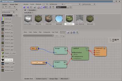
19. Press and hold the left mouse button on the out port of the Image1 node and drag the cursor to the Lambert node; a flyout is displayed. Choose transparency from it; a connection is established between the Image1 and Lambert nodes. Figure 10 shows the node networks in the Material Manager window. Close the Material Manager window.

Figure 10
20. Choose Render > Render > Preview from the menu bar. The render out is displayed in the Default_Pass-1920x1080 (Display Scale 1:2) window, as shown in Figure 11.

Figure 11
21. Choose Model > Get > Primitive > Polygon Mesh > Sphere from the menu bar; the Scene_Root : sphere (General) property editor is displayed. Enter sky in the Name edit box.
22. In the Sphere property set, enter 100 in the Radius edit box.
23. In the Geometry property set, enter 12 in the U and V edit boxes of the Subdivision area.
25. Make sure the sky is selected in the Explorer window. Choose Render > Property > Texture Projection > Cylindrical from the menu bar and then apply the cloudy_sky.jpg to sky in the Camera viewport as discussed earlier. Figure 12 shows sky in the scene.

Figure 12
26. Choose Model > Primitive > Light > Infinite from the menu bar; the Infinite light is added to all viewports and the Scene_Root : Infinite (General |Rendering) property editor is displayed.
27. In the Scene_Root : Infinite (General |Rendering) property editor, enter 0.348 in the Intensity edit box in the Colors area. Next, select the Enabled check box in the Shadows area and enter 0.07 in the Umbra edit box. Now, close the property editor.
28. Make sure the Infinite light is selected in the Explorer window. Now, create a copy of Infinite light using CTRL+D and set intensity to 0.3.
29. Choose Model > Primitive > Light > Point from the menu bar; the Infinite light is added to all viewports and the Scene_Root : Point (General |Rendering) property editor is displayed.
30. In the Scene_Root : Point (General |Rendering) property editor, enter 0.136 in the Intensity edit box in the Colors area. Next, select the Enabled check box in the Shadows area and enter 0.019 in the Umbra edit box. Close the property editor. Now, Align the lights in the scene using Translate Tool. The alignment of the lights are displays in the Figure 13.

Figure 13
31. Select the Ground1 from the Explorer window. Press CTRL+2; the Hair toolbar is displayed. Choose Hair > Create > Hair from the main toolbar; a flyout is displayed.
32. Choose From Selection from the flyout; the hair is created on Ground1 and the Scene_Root : Hair : Hair property editor is displayed, as shown in Figure 14.
 |
| Figure 14 |
 |
| Figure 15 |
34. Choose Strand from the Main Command Panel. Now, press and hold the left mouse button and drag the cursor over some part of the Grass in the Camera viewport; the strands of the Grass are selected in the Viewport.
36. Similarly, select other Stands of Grass strands in the Camera viewport and set their length randomly by using the Scale tool, refer to Figure 16.

Figure 16
Next, you will add style to the grass strands by using the Brush tool.37. Choose Tip from the Main Command Panel. Now, press and hold the left mouse button and drag the cursor over some part of the Grass in the Camera viewport; the tips of the Grass are selected in the Viewport.
38. Choose Brush from the Hair toolbar; the shape of the cursor is changed. Next, press and hold down the left mouse button and drag the cursor; the selected Grass tips are brushed in various directions. Next, select other strands and add style to them as well, as shown in Figure 17.

Figure 17
Next, you will apply the shader to grass.39. Press SPACEBAR to invoke the Object mode. Select Grass from the Explorer window. Choose Hair > Modify > Shader from the main toolbar; the Hair_Material : Hair_Renderer (Rendering) property editor is displayed.
40. In the Ambient area, enter 0.392, 0.400, and 0.224 in the R, G, and B edit boxes, respectively, corresponding to the Color parameter.
41. In the Diffuse area, enter 0.345, 0.463, and 0.251 in the R, G, and B edit boxes, respectively, corresponding to the Root Color parameter.
42. In the Tip Colors area, enter 0.345, 0.463, and 0.251 in the R, G, and B edit boxes, respectively, corresponding to the Color A parameter and then enter 0.231, 0.325, and 0.157 in the R, G,and B edit boxes, respectively, corresponding to Color B parameter.
43. In the Hair_Material : Hair_Renderer (Rendering) property editor, enter 28.125 and 12.5 in the Root(%) and the Tip (%) edit boxes, respectively. Enter 0.512 in the Center and Range edit boxes in the Root/Tip Crossover area and then enter 0.75 in the Color variation edit box. Now, close the property editor.
44. Set the view angle in the Camera viewport. Choose Render > Render > Preview from the menu bar. The final output of the scene is displayed in the Default_Pass 1280*720 (Display Scale 1:2) window, as shown in Figure 18.

Figure 18
No comments:
Post a Comment