In this tutorial, you can create the falling maple leaves simulation in Softimage.
1. Choose Model > Get > Primitive > Polygon Mesh > Grid from the menu bar; the Scene_Root : grid(General) property editor is displayed and grid is created in the Camera viewport. Next, close the property editor and set the values of the following parameters in the Transform subpanel of Main Command Panel:
s area
x: 2.2266 y: 1.5243 z: 1.5243
r area
x: -4.6074
t area
x: -2.6903 y: -1.2479 z: -5.9822
2. Make sure that the grid is selected in the Camera viewport. Next, press CTRL+D; the duplicate copy of grid is created with the name grid1 in the Camera viewport. Choose Scene button from the Main Command Panel; a flyout is displayed. Notice that the grid and grid 1 is displayed in the flyout.
3. Make sure that the grid1 is selected in the flyout. Now, set the values of the following parameters in the Transform subpanel of Main Command Panel:
s area
x: 3.5018 y: 3.5018 z: 2.1301
r area
x: 89.8455
t area
y: 4.0479 z: -11.8129
After entering the value gird and grid1 is aligned in the Camera viewport, as shown in
Figure 1.
 |
| Figure 1 |
4. Choose Model > Get > Primitive > Polygon Mesh > Grid from the menu bar; the Scene_Root : grid2(General) property editor is displayed and grid2 is created in the Camera viewport. Next, press R to activate the Scale Tool and scale grid2.Next, press V to activate the Translate Tool and move grid2 along the Y direction in the Camera viewport, refer to Figure 2.
 |
| Figure 2 |
5. Make sure the grid2 is selected in the Camera viewport. Choose ICE > Particles > Create > Falling Leaves from the menu bar; the Scene_Root : Falling_Leaves_PontCloud : Point Cloud : Falling Leaves property editor is displayed in the Camera viewport.
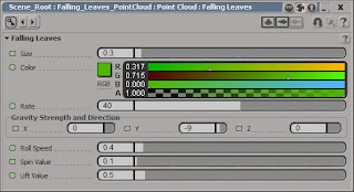
6. In the Scene_Root : Falling_Leaves_PontCloud : Point Cloud : Falling Leaves property editor, enter 0.3 in the Size edit box of the Falling Leaves area and -9 in the Y edit box of the Gravity Strenght and Direction area, as shown in Figure 3. Now, close the property editor.
 |
| Figure 3 |
 |
| Figure 4 |
8. Select grid2 in the Camera viewport. Choose ICE > Particles > Create > Rigid Bodies from the menu bar; the grid2 is converted to rigid body. Next, choose ICE > Particles > Force > Gravity from the menu bar; the gravity force is applied.
10. Select the falling leaves in the Camera viewport. Alternatively, Choose Scene button from the Main Command Panel; a flyout is displayed. Notice that the grid and grid 1 is displayed in the flyout. Expand the Falling_Leaves_PointCloud > Point Cloud > ICETree > Decendant Nodes from the flyout. Choose Falling Leaves from the expanded Decendant Nodes.
11. Choose ICE > Particles > Collision > Stick to Surface from the menu bar; the shape of the cursor changes in the Camera viewport. Next, click on grid in the Camera viewport. Now, choose the Play Forward button to start the simulation. Notice that the leaves are collide with grid in Camera viewport, refer to Figure 5.
 |
| Figure 5 |
12. Select grid1 in the Camera viewport and choose Model > Material > Lambert from the menu bar; the grid1 : Material# : Lambert property editor is displayed. Choose the Diffuse Connector corresponding to the Diffuse prameter in the property editor; a flyout is displayed. Choose Image from the flyout; the Material# : Image property editor is displayed.
13. In the Material# : Image property, choose the New button from the Image area; a flyout is displayed. Choose New From File from the flyout; the New Image Clip dialog box is displayed. Choose imagenes-de-paisajes-landscapes-photography_10 from the dialog box and choose the OK button; the dialog box is closed. In the grid1 : Material# : Lambert property editor, choose the New button in the Texture Projection area; a flyout is displayed. Choose Cube from the flyout; the texture is projected on the grid1 in the Camera viewport, as shown in Figure 6. Close the property editor.
 |
| Figure 6 |
http://www.hdwallpaperspk.com/landscape-wallpapers/imagenes-de-paisajes-landscapes-photography_10/
14. Select the grid in the Camera viewport. Next, choose Model > Material > Lambert from the menu bar; the grid : Material# : Lambert property editor is displayed. Now, close the property editor.
15. Choose Render > Metarial > Modify > Materials from the menu bar; the Matreial Manager window is displayed, refer to Figure 7.
 |
| Figure 7 |
 |
| Figure 9 |
18. Click on the out port of the Lambert node and then drag the cursor on the Matte_Shadow_mip(mr Surface Material Shader) node; a flyout is displayed. Choose background from the flyout. The Lambert node is connected with the Matte_Shadow_mip(mr Surface Material Shader) node, as shown in Figure 10. Double-click on the Lambert node in the Render Tree workspace; the Material#: Lambert property editor is displayed.
 |
| Figure 10 |
20. To add the light, choose Model > Get > Primitive > Light > Infinite from the menu bar; the Infinite light is added in the Camera viewport. Press V to activate the Translate Tool and move the light along the Y direction.
21. Choose the Play Forward button from the Playback Controls area; the simulation starts. Press Q and draw the render region in Camera viewport for the final output, as shown in Figure 11.
 |
| Figure 11 |

No comments:
Post a Comment